

Transfer Route Planning
AILV MATERIALS · PRODUCT SELECTION
Fit the cabinet to the complete transfer route
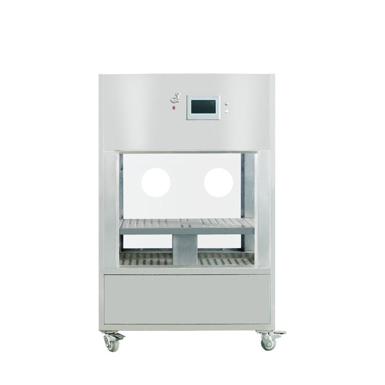
A transport cabinet must move between the sending and receiving work areas. Review the cabinet footprint, load space and docking position against the actual route, including doorways and turning points.
Published Equipment Options
The worktop can be raised and lowered to meet the docking needs of different heights
Super UPS power supply, long working time
Man-machine dialogue operation screen, powerful
Vertical flow and horizontal flow are optional
Walk the route on the drawing
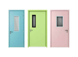
Check the narrowest doorway and the space required to turn or park. Compare the loaded cabinet with each point where operators need to open, move or unload it.
Match the receiving position
Identify the loading height and the interface with the receiving equipment. Keep the docking requirement alongside the chamber dimensions so the complete transfer can be reviewed.
Specify operation while moving
Record the selected airflow, controls and power arrangement with the operating procedure. Include the service access needed when the cabinet is parked between transfer activities.
Technical Index
Shell: 304 stainless steel metal plate bent.
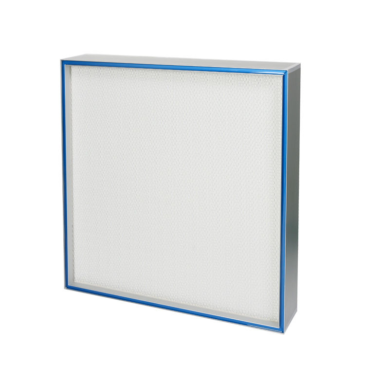
Filter: G4 primary filter and H14 high efficiency filter.
DOP port: The DOP test port upstream of the HEPA filter to test the integrity of the HEPA filter.
Maneuverability: Rotating (360°) casters with brakes.
Product Drawing

Standard Size and Basic Performance Parameters
|
Model number |
Overall dimension L×W×H |
Work area size L×W×H |
The value of the outlet determines the wind speed(m/s) |
Cleanliness of work area |
Power supply(kw) |
|
BSL-LUFT8-072058 |
800×600×1800 |
720×580×750 |
0.45±20% |
Level A |
0.4 |
|
BSL-LUFT10-092058 |
1000×600×1800 |
920×580×750 |
0.4 |
||
|
BSL-LUFT14-112068 |
1200×700×1800 |
1120×680×750 |
0.5 |
Note: The specifications listed in the table are for customers' reference only. Class A unidirectional flow carriage can be designed and manufactured according to customers' URS.
▤ Include the selected cabinet reference, load dimensions, docking height, quantities and operating arrangement. Check doorways, route clearance and service access against the transfer plan.



 Home
 Products
 Contact
 News