
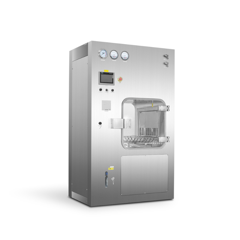


VHP Transfer Planning
AILV MATERIALS · PRODUCT SELECTION
Plan the transfer load and treatment sequence together
A VHP pass box connects a transfer chamber with a specified treatment process. The intended load, packaging and operating sequence should be defined before the chamber and service requirements are agreed.
Published Configuration Notes
Clean compressed air is used as the power source to reduce indoor air extraction, fast dehumidification, reduce the total sterilization time, and reduce the risk of condensation in the cabin.
The decomposition filter can effectively reduce the VHP concentration during discharge and reduce the impact on the environment and personnel.
It can be repaired up and down to reduce the reserved maintenance space.
It can do rotation sterilization transmission, increase the utilization rate of plant space, and improve the process layout.
The chamber can be tested for tightness, and the sterilization process can be started after passing the test.
The batch number should be entered before sterilization for easy traceability.
The sterilization effect meets the requirements of GMP.
Describe the load
List the items, packaging and loading pattern that the chamber must accommodate. Check door access and the receiving-room interface against the intended movement of those items.
Identify the agreed process
State the required treatment sequence and process records in the equipment brief. Keep the load and cycle requirements together when reviewing the proposed controls and operating arrangement.
Reserve space for service
Locate the required utilities and maintenance route on the installation drawing. The chamber position should leave access for the selected service arrangement and the surrounding room equipment.
Sterilization Process
Air Tightness Test -- Dehumidification -- H2o2 Gasification Sterilization -- Discharge Residue -- End
Evaporator Drawing

Standard Size and Basic Performance Parameters
|
Model number |
Overall dimensionW×H×D |
Work area size W×H×D |
Rated volume(L) |
Cleanliness of work area |
Sterilizing potency |
Power supply(kw) |
|
BSL-LATM288 |
1200×800×2000 |
600×800×600 |
288 |
Grade B |
6-log |
3 |
|
BSL-LATM512 |
1400×800×2200 |
800×800×800 |
512 |
|||
|
BSL-LATM1000 |
1600×1060×2100 |
1000×1000×1000 |
1000 |
|||
|
BSL-LATM1440 |
1600×1260×2300 |
1000×1200×1200 |
1440 |
Note: The specifications listed in the table are for customer's reference only and can be designed and manufactured according to customer's URS.
▤ List the transfer load, packaging, chamber access and quantities. Include the required treatment sequence, utility connections and acceptance documents with the proposed AILV equipment package.




 Home
 Products
 Contact
 News